Untuk mendapatkan kedalaman yang diharapkan diperlukan suatu alat yang letaknya
di ujung rangkaian pipa pemboran dinamakan mata bor atau bit. Mata bor atau bit
adalah alat yang terpasang di ujung paling bawah dari rangkaian pipa yang
langsung berhadapan dengan formasi atau batuan yang di bor. Adanya putaran dan
beban yang diperoleh dari rangkaian pipa bor diatasnya, akan menyebabkan mata
bor itu menghancurkan batuan yang terletak dibawah sehingga akan menembus
semakin dalam bebatuan tersebut. Lumpur yang disirkulasikan akan keluar melalui
mata bor dan menyemprotkan langsung kebatuan yang sedang dihancurkan di dasar
lubang bor. Semprotan ini akan ikut membantu menghancurkan batuan-batuan itu.
Batuan yang disemprot oleh Lumpur tadi akan lebih mudah lagi dihancurkan oleh
mata bor, sehingga dengan demikian akan diperoleh laju pemboran yang lebih
cepat.
Tampilkan postingan dengan label Perminyakan. Tampilkan semua postingan
Tampilkan postingan dengan label Perminyakan. Tampilkan semua postingan

Measurement Calculation for Directional Well
Lama gak nulis, coz udah sibuk keluar masuk hutan dan gunung
kali ini w akan coba nulis lagi masalah perhitungan survey pada sumur directional, ini juga karena ada yang tanya kenapa bisa nilai Vertical Section jadi negatif saat dihitung, hmmmm cukup bikin pusing juga apalagi yang tanya juga baru mulai nyelesaikan Tugas Akhir
& karena waktu w Kerja Praktek juga ambil judul sama ya harus bisa jawab deh.... padahal udah lupa ^^!
ok pertama liat file yang w lampirin di www.Scribd.com tenang w link kok
Directional Drilling Equation
kali ini w akan coba nulis lagi masalah perhitungan survey pada sumur directional, ini juga karena ada yang tanya kenapa bisa nilai Vertical Section jadi negatif saat dihitung, hmmmm cukup bikin pusing juga apalagi yang tanya juga baru mulai nyelesaikan Tugas Akhir
& karena waktu w Kerja Praktek juga ambil judul sama ya harus bisa jawab deh.... padahal udah lupa ^^!
ok pertama liat file yang w lampirin di www.Scribd.com tenang w link kok
Directional Drilling Equation
Test untuk Lumpur Pemboran
Sharing system lumpur bor dan test untuk lumpur bor, n karena halaman ini gak bisa di kopi pasting, gw taro aja di tempat laen tapi bisa di download kok
semoga bermanfaat
Mud Test
Introduction
semoga bermanfaat
Mud Test
Introduction
Pengetahuan Umum Perminyakan
Catatan teknik produksi I
dari pada ilang lagi susah nyarinya gw tao aja disini deh
Source : Dosen Akamigas Balongan "Heru Herawan"
Underbalance drilling
Materi Teknik Produksi II dari pak Heru dari pada gw taro di flash disk/ hard disk ilang lagi mendingan gw taro disini
Source : Dosen Akamigas Balongan "Heru Herawan"
Applications Related to Wellbore-Proximity Mechanics
Wellbore Stability during Drilling
Most wellbore stability problems occur in shale formations. Unfortunately, shale properties range from very soft to very hard, and from very laminated to very intact. Several mechanisms cause wellbore instability problems (Figure 5-5); chemical and mechanical effects will be discussed in this section.

Chemical Effects
Ion-exchanging clays, such as illite, mica, smectite, chlorite, mixed-layerclays, and zeolites, can cause many wellbore instability problems. Engineers may erroneously try to model failure mechanisms with analytical or empirical mechanical models while the main mechanism may be failure because of chemical effects. The following failure mechanisms during wellbore construction can be related to chemical causes.
Clay Swelling (Hydration) and Migration
Most shale formations contain water-sensitive clay materials such as smectite, illite, and mixed-layer clays, which absorb water that induces an elevated localized pressure. This pressure reduces the effective stress around the wellbore, which causes the shale matrix to swell, disintegrate, and collapse (Dusseault and Gray, 1992). Mody and Hale (1993) developed a model that incorporated mechanical and chemical effects to evaluate the
drilling fluid on shale stability.
Ion Exchanging
Brines such as KCl can control clay swelling, but illite, chlorite, smectite, and mixed-layer clays can change the brine through ion-exchanging mechanisms and swell afterward.
Cementation Deterioration
When examining sand formations, engineers must study the degree and type of cementation. Mineralogical analysis, thin-section petrography, and fluid compatibility are viable testing methods for evaluating sand production.
Near-Wellbore Damage
Near-wellbore formation damage can occur because of paraffin deposits, scale deposits, fines migration caused by kaolinite and illite clays, asphaltene precipitation, sand production, emulsions induced by iron, formation of oil emulsions by acid in combination with soluble iron, iron-compound precipitation, and even emulsions formed from fracturing fluids during stimulation.
To overcome these chemical effects, engineers should select the type of drilling-fluid system based on its effect on formation strength. The effects of the chemical and physical properties of the drilling-fluid system on formation stability should be lumped and the drilling-fluid system should be evaluated on the basis of rock mechanics. The following example shows an easy technique that would lump all chemical effects and evaluate the drilling-fluid systems based on rock mechanics.
Example: Drilling-Fluid Selection—A Rock Mechanics Perspective
Available Data
Six drilling-fluid samples are being evaluated for use through a shale segment that exhibited many instability problems during drilling. Show how these systems can be evaluated on the basis of rock mechanics.
Solution
The core samples should be preserved after coring, and no cleaning or drying processes should be conducted. The samples should be brought to their estimated in-situ stress fields at a suggested value of the confining pressure (Pc = Pw - Pr). The same strain rate (for example, 10-4 sec-1) or the same loading rate (for example 5 to 10 psi/sec) should be used for all tests. The samples should be cut in the same manner and same direction (vertically or horizontally). Two samples for each drilling-fluid system and two samples with no drilling fluid should be tested for repeatability. Two samples should be saturated in each drilling-fluid system for the same length of time (for example, 1 month) in addition to the two other samples that should be left in closed jars as the base samples. This procedure is applied to optimize the drilling-fluid system based on the compressive strength and Young's modulus reduction obtained for these systems. The results are given in Figure 5-6.

Figure 5-6 The effect of different drilling fluid systems on the
mechanical properties of shale samples
System 5 was selected to drill the given shale section. Notice how both the compressive strength and Young's modulus were affected by the different drilling-fluid systems.
Mechanical Effects
Tensile and shear failure mechanisms should be considered for wellbore stability evaluation during drilling.
Tensile Failure
The effective stress at the wellbore exceeds the tensile strength of the formation and causes tensile failure. Therefore, an induced fracture can result because of drilling-fluid loss if
For an elastic medium, this is given by (Haimson and Fairhurst, 1967)
However, if a natural fracture exists, then the tensile strength, T, should be assumed to be zero.
Shear Failure
Once a wellbore is drilled and a stress concentration field is established, the rock will either withstand the stress field or yield, resulting in a near wellbore breakout zone that causes spalling, sloughing, and hole enlargement. An appropriate failure criterion should be used for evaluation of this type of failure.
Drilling-Fluid Weight
Drilling-fluid weight should be calculated as a means of preventing the initiation of tensile and shear (plastic) failures. In some formations, the drilling-fluid weight should prevent creeping in viscoplastic formations, such as salt rock. Drilling-fluid weight is an important consideration for treating wellbore instability problems. The drilling-fluid weight is limited by two boundaries:
• The upper boundary is the pressure that causes tensile failure and
drilling-fluid loss. This pressure can be determined in the field based
on Equation 5-44.
• The lower boundary is the pressure required to provide confining stress, which is removed during drilling. The confining stress prevents shear failure, the creation of a plastic zone, and plastic flow (creep).
The upper boundary is estimated from the in-situ stress field, and the tensile strength is measured in the laboratory. While the lower boundary is estimated from the in-situ stress field
Most wellbore stability problems occur in shale formations. Unfortunately, shale properties range from very soft to very hard, and from very laminated to very intact. Several mechanisms cause wellbore instability problems (Figure 5-5); chemical and mechanical effects will be discussed in this section.

Chemical Effects
Ion-exchanging clays, such as illite, mica, smectite, chlorite, mixed-layerclays, and zeolites, can cause many wellbore instability problems. Engineers may erroneously try to model failure mechanisms with analytical or empirical mechanical models while the main mechanism may be failure because of chemical effects. The following failure mechanisms during wellbore construction can be related to chemical causes.
Clay Swelling (Hydration) and Migration
Most shale formations contain water-sensitive clay materials such as smectite, illite, and mixed-layer clays, which absorb water that induces an elevated localized pressure. This pressure reduces the effective stress around the wellbore, which causes the shale matrix to swell, disintegrate, and collapse (Dusseault and Gray, 1992). Mody and Hale (1993) developed a model that incorporated mechanical and chemical effects to evaluate the
drilling fluid on shale stability.
Ion Exchanging
Brines such as KCl can control clay swelling, but illite, chlorite, smectite, and mixed-layer clays can change the brine through ion-exchanging mechanisms and swell afterward.
Cementation Deterioration
When examining sand formations, engineers must study the degree and type of cementation. Mineralogical analysis, thin-section petrography, and fluid compatibility are viable testing methods for evaluating sand production.
Near-Wellbore Damage
Near-wellbore formation damage can occur because of paraffin deposits, scale deposits, fines migration caused by kaolinite and illite clays, asphaltene precipitation, sand production, emulsions induced by iron, formation of oil emulsions by acid in combination with soluble iron, iron-compound precipitation, and even emulsions formed from fracturing fluids during stimulation.
To overcome these chemical effects, engineers should select the type of drilling-fluid system based on its effect on formation strength. The effects of the chemical and physical properties of the drilling-fluid system on formation stability should be lumped and the drilling-fluid system should be evaluated on the basis of rock mechanics. The following example shows an easy technique that would lump all chemical effects and evaluate the drilling-fluid systems based on rock mechanics.
Example: Drilling-Fluid Selection—A Rock Mechanics Perspective
Available Data
Six drilling-fluid samples are being evaluated for use through a shale segment that exhibited many instability problems during drilling. Show how these systems can be evaluated on the basis of rock mechanics.
Solution
The core samples should be preserved after coring, and no cleaning or drying processes should be conducted. The samples should be brought to their estimated in-situ stress fields at a suggested value of the confining pressure (Pc = Pw - Pr). The same strain rate (for example, 10-4 sec-1) or the same loading rate (for example 5 to 10 psi/sec) should be used for all tests. The samples should be cut in the same manner and same direction (vertically or horizontally). Two samples for each drilling-fluid system and two samples with no drilling fluid should be tested for repeatability. Two samples should be saturated in each drilling-fluid system for the same length of time (for example, 1 month) in addition to the two other samples that should be left in closed jars as the base samples. This procedure is applied to optimize the drilling-fluid system based on the compressive strength and Young's modulus reduction obtained for these systems. The results are given in Figure 5-6.

Figure 5-6 The effect of different drilling fluid systems on the
mechanical properties of shale samples
System 5 was selected to drill the given shale section. Notice how both the compressive strength and Young's modulus were affected by the different drilling-fluid systems.
Mechanical Effects
Tensile and shear failure mechanisms should be considered for wellbore stability evaluation during drilling.
Tensile Failure
The effective stress at the wellbore exceeds the tensile strength of the formation and causes tensile failure. Therefore, an induced fracture can result because of drilling-fluid loss if
For an elastic medium, this is given by (Haimson and Fairhurst, 1967)
However, if a natural fracture exists, then the tensile strength, T, should be assumed to be zero.
Shear Failure
Once a wellbore is drilled and a stress concentration field is established, the rock will either withstand the stress field or yield, resulting in a near wellbore breakout zone that causes spalling, sloughing, and hole enlargement. An appropriate failure criterion should be used for evaluation of this type of failure.
Drilling-Fluid Weight
Drilling-fluid weight should be calculated as a means of preventing the initiation of tensile and shear (plastic) failures. In some formations, the drilling-fluid weight should prevent creeping in viscoplastic formations, such as salt rock. Drilling-fluid weight is an important consideration for treating wellbore instability problems. The drilling-fluid weight is limited by two boundaries:
• The upper boundary is the pressure that causes tensile failure and
drilling-fluid loss. This pressure can be determined in the field based
on Equation 5-44.
• The lower boundary is the pressure required to provide confining stress, which is removed during drilling. The confining stress prevents shear failure, the creation of a plastic zone, and plastic flow (creep).
The upper boundary is estimated from the in-situ stress field, and the tensile strength is measured in the laboratory. While the lower boundary is estimated from the in-situ stress field
Introduction of Petroleum Refinery OperationP
A petroleum refinery is a manufacturing operation where crude petroleum, the raw material, is converted into usable finished products. In other words, it is the manufacturing phase of the oil industry. This chapter presents a general introduction to overall refinery operations as a forerunner to the detailed information on specific processes and products which follows, and the technologies that are applied to pressure relief operations. Other chapters cover the major operations and processes used in refining, and discuss the critical properties and end uses of the products. However, it should be emphasized that a refinery is only one of the major phases of the petroleum industry; others being exploration, production, transportation, and marketing, and a variety of feedstock chemicals that supply the raw materials for various product lines. Research and engineering might also be listed, but they are, in reality, a necessary and integral part of each of the phases.
REFINERY OPERATIONS
The function of the refinery is to convert crude oil into the finished products required by the market in the most efficient, and hence most profitable manner.
2 Pressure Safety Design Practices
The methods employed necessarily vary widely from one refinery to another, depending on the crude processed, the nature and location of the market, the type of equipment available, and many other factors. However, for simplification, it may be considered that all refining processes fall into one of four basic categories.
The first category is fractionation or distillation. This method of physically separating a mixture of compounds was the earliest process used in petroleum refining, and today is still one of the most important. However, since it is not generally possible to separate the complex petroleum mixtures into individual compounds, such mixtures are segregated into fractions or "cuts", each of which is characterized by a carefully controlled boiling range. These cuts are then further processed or utilized in the refinery operations.
The second basic type of process, essentially chemical in nature, consists of converting or chemically transforming certain of these "cuts" into products of higher commercial value. There are many ways of doing this, but all consist fundamentallyof altering the molecular structure of the components. In the case of a heavy oil, the molecules may be cracked to form lighter, more valuable products, as for instance in catalytic cracking and coking. On the other hand, gaseous products may be polymerized or otherwise combined to form liquid products which may be blended into gasoline. With certain processes, e.g. catalytic reforming, both cracking and polymerization take place concurrently with the more desirable de-hydrogenation, hydrogenation, and isomerization reactions. The net result of all these transformationsis the production of mixtures containing new arrays of hydrocarbons of higher value than the starting materials.
Nearly all the fractions produced by the processes mentioned above contain certain objectionable constituents or impurities. The third basic category is, therefore, treating. This group of processes includes the removal of the unwanted components, or their conversion to innocuous or less undesirable compounds. Removal of the impurities is sometimes accomplished by physical treating, as exemplified by the process for manufacturing kerosene, wherein sulfur and certain undesirable hydrocarbons are removed by extraction with liquid sulfur dioxide. Alternatively, the removal may be carried out by converting the unwanted compounds to a form more readily removed as is done in the hydrodesulfurization of diesel fuel. Here the sulfur compounds are cracked and hydrogenated. The sulfur is converted to hydrogen sulfide which can be readily separated from the heavier diesel oil by fractionation. An example of the conversion of undesirable components to innocuous compounds which remain in the product is found in the gasoline sweetening processes. There the mercaptans present give the product a foul, objectionable odor. The sweetening process
Introductionto Petroleum Refinery Operations 3 merely transforms the mercaptans to organic disulfides which are less objectionable.
Although sulfur is perhaps the commonest and most troublesome of the impurities found in petroleum, it is certainly not the only one. Substances such as nickel, vanadium, and nitrogen may also be present in the crude oil. These impurities are undesirable because of the difficulty they cause during processing in the refinery or because of some detrimental effect during consumer use of the product. Furthermore, presence of certain hydrocarbons or certain types of hydrocarbons may lower the quality of a specific product. It was mentioned that aromatics are removed from kerosene by SO, extraction. The aromatics have undesirable burning characteristics and hence the product quality is improved if these "impurities" are removed. Lube oil treating process such as dewaxing, deasphalting, and phenol treating also fall into this category.
The fourth basic category is blending of the finished cuts into commercially saleable products such as motor gasoline, kerosene, lubricating oils, and bunker fuel oil, according to their specifications.
These four basic categories encompass the fundamental operation of a refinery. All other activities are carried out to implement them. The specificationsfor a given product are established to insure a satisfactory level of product performance. Specifications can be altered from time to time, but a product normally must meet the then existing product specifications. Various crudes on the other hand yield fractions with significantly different properties. At first glance, it might appear reasonable to select crudes to best match the product needs of each refinery. Many times, however, this is not economical as the money saved in eliminating various conversion and treating processes is offset by other factors. These might include crude availability, price, and transportation or specialty product requirements. A refinery is a sophisticated multi-component process operated in overall balance. The balance is set by economic considerationswith the major variables being crude oil, process costs, and final products. It is thus easier to see why (1) no two refineries are exactly alike, (2) various conversion and purification processes are required, and (3) crude selection is important.
TYPES OF REFINERIES
Each refinery is designed to manufacture products as economically as possible based on the best knowledge available with regard to end product needs, future expansion plans, crude availability and other pertinent factors.
4 Pressure Safety Design Practices
A basic modern refinery which does not produce lubricating oils or chemicals is commonly referred to as a fuel products refinery. It is designed to produce primarily motor gasoline, distillate fuels (diesel oil, jet fuel, and heating oil), and bunker (residual) fuel oil. The fuel products refineries can be considered basic and minimum as regards refinery product and processing requirements. Hydroskimming and conversion are the two major variations of this type refinery. There is a wide range of conversion levels. The term maximum conversion type has no precise definition but is often used to describe a level of conversion , where there is no net fuel oil manufacture. A fuel products refinery with specialities may manufacture lubricating oils, asphalts, greases, solvents, waxes and chemical feed stocks in addition to the primary fuel products. The number and diversity of products will naturally vary from one refinery to another.
Refineries produce chemical feed stocks for sale to the chemical affiliates and do not have responsibility for the manufacture of chemical products directly. Both operations may be carried out at the same physical location but the corporate product responsibilities are usually separate.
FUEL PRODUCTS REFINERY
Hydroskimmer
A hydroskimmingrefinery lends itself to locations where the market demands for the major fuel products (gasoline, gas oil, and residual fuel oil) approximate the quantities of these products obtainable by distillation from the available crudes. A typical hydroskimming refinery would include the following:
1. Atmospheric Pipestill
2. Powerforming (Catalytic Naphtha Reforming)
3. Light Ends Recovery - Fractionation
4.Treating and Blending
Figure 1 shows a simplified flow plan for a typical hydroskimming refinery. The atmospheric pipestill performs the initial distillation of crude oil into gas, naphtha, distillates, and residuum. The naphtha may be separated into gasoline blending stock, solvents, and Powerformer feed. The distillates include kerosene, jet fuel, heating oil and diesel oil. The residuum is blended for use as bunker fuel oil.
The Powerforming unit is required to upgrade virgin naphtha to produce high octane gasoline. Powerforming is a fixed bed catalytic reforming process employing a regenerable platinum catalyst. In the process, a series of reactions

6 Pressure Safety Design Practices
takes place. The most important of these is aromatization; other reactions include isomerization, cracking, hydrogenation, and polymerization. The desired product is of approximately the same boiling range as the feed, but the molecules have been rearranged or reformed into higher octane compounds.
Light ends recovery and fractionating equipment is necessary after the Powerformer and on the pipestill overhead stream to separate the effluent mixtures into the desired boiling range cuts.
Hydrofining is used to reduce sulfur and/or other impurities and to improve odor, color, and stability of the pipestill fractions. Hydrofining is a fixed-bed catalytic process using a regenerable cobalt molybdate catalyst in a hydrogen atmosphere. The hydrogen is produced by the Powerformer with supplemental hydrogen manufactured if necessary. The difficulty of hydrofining
(desulfurization) increases with increase in the hydrocarbon boiling point. Naphthas are generally desulfurized up to 99+ % by hydrofining while the maximum desulfurization of distillates is usually 90 % .
The components produced by the process sequence outlined above are blended as required to meet final product rates and qualities.
Conversion
The hydroskimming type refinery is used where the gasoline demand is substantiallylower and hence the final product demand is close to that yielded by single stage distillation. In areas where the demand for gasoline is relatively high, conversion processing is required. The minimum processes for a fuel products refinery designed would typically include:
1. Atmospheric and Vacuum Crude Distillation
2. Catalytic Gas Oil Cracking
3. Powerforming
4. Light Ends Recovery - Fractionation
5. Treating and Blending
Figure 2 shows a simplified flow plan for a typical conversion typerefinery. The atmospheric P/Sresiduum can be fed to a vacuum pipestill. The vacuum tower enables the refiner to cut deeper into the crude, at the same time avoiding high temperatures (above about 750 OF) which cause thermal cracking with resultant deposition of coke and tarry residues in the equipment.
The vacuum gas oil produced by vacuum distillation is fed to a catalytic

8 Pressure Safety Design Practices
crackmg unit for conversion into high octane gasoline blending stock. Byproducts are gas, distillate, cycle gas oil, and fractionator bottoms. The process uses a fluidized catalyst system. The catalyst is circulated continuously between the reactor where cracking takes place and the regenerator where the coke deposited on the catalyst is burned off. The major competing process is hydrocracking which offers greater conversion and flexibility but usually requires a higher investment.
Hydrocracking is a fixed bed catalytic process which cracks and hydrogenates hydrocarbon feeds. The process consumes large quantities of hydrogen and a hydrogen plant is usually necessary to support the operation. Practically any stock can be hydrocracked, including refractory feeds which resist conversion by other processes. In general, the very heavy residuum from the vacuum pipestill does not make good quality feed for catalytic cracking. In the refinery shown it is blended into residual fuel oil. Many times, however, the market for large volumes of residual fuel oil does not exist. When this is the case, additional conversionunits are added to further process the vacuum pipestill bottoms. In other words, the higher the conversion of the refinery the more lighter fractions are produced. The relative levels of conversion vary from refinery to refinery.
A typical maximum conversion type refinery is shown in Figure 3. The higher conversion levels are obtained by ad&tional processing of the bottoms and/or light ends. To increase conversion of the bottoms the amount and/or severity of processing is increased. The resulting fuel oil levels may decrease to zero. Included here in addition to the basic components of a conversion refinery may be fluid coking, delayed coking, and/or visbreaking. These processes are basically thermal cracking processes for reducing the volume and viscosity of the vacuum residuum while producing appreciable quantities of lighter products.
Each of the three processes is commercially used with selection based on particular needs at a given refinery. Some of the various characteristics include:
1. Coking-Delayed Coking and Fluid Coking are the two major variations of this process. Fluid coking produces less coke as compared with delayed coking and hence yields a better product distribution. That is, for a given product slate less crude is converted into coke. The coke produced by fluid coking, however, is of little value as it consists of fine hard particles in contrast to large pieces for delayed coke. This difference in size and texture is important to electrode manufacturers who historically have used delayed coke.
2. Visbreaking is the least expensive of the cracking processes but is limited to the lowest conversion of perhaps 20 to 25% of the feed to 680 "F material.

10 Pressure Safety Design Practices
To obtain light ends conversion, alkylation and polymerization are used to increase the relative amounts of liquid fuel products manufactured. Alkylation converts olefins, (propylene, butylenes, amylenes, etc.), into high octane gasoline by reacting them with isobutane. Polymerization involves reaction of propylene and/or butylenes to produce an unsaturated hydrocarbon mixture in the motor gasoline boiling range.
An old variation of the conversion type is a catalytic combination unit. Development of this scheme was necessitated by the rising cost of refinery construction after World War I1 and by the great demand for capital for postwar expansion. The scheme reduced the investment and operating costs for refining equipment. The basic feature of the combination unit lies in the integration of the fractionation facilities of the reduced crude distillation and catalytic cracking sections.
A FUEL PRODUCTS REFINJ3RY WITH SPECIALTIES
A fuel products refinery with specialties may manufacture products such as lubricating oils, asphalts, greases, solvents, waxes and chemical feed stocks in addition to the primary fuel products. The number and diversity of products will naturally vary from one refinery to another, but for purposes of discussion a fuel products refinery with specialties may include many of the following processes.
1. Two-Stage Crude Distillation (Atmospheric and Vacuum) - The vacuum stage can be used alternately to produce heavy gas oil for catalytic cracking feed or raw lube distillate cuts for lubricating oil manufacture.
2. Virgin Naphtha Catalytic Reforming (Powerforming) - This technique is used for the production of high octane motor gasoline, or as a source of aromatic compounds.
3. Light Ends Recovery, Fractionation, and Conversion - Propylenes and butylenes may be recovered for feed to a polymerization plant for production of high octane gasoline; or chemicals. Butylenes and isobutane may be desired for use in an alkylation plant where they are combined to make aviation gasoline and motor gasoline blendstocks. Propanes and butanes may be recovered in essentially pure form for sale as liquefied petroleum gases. It may be profitable to recover ethylene for chemical production. Certain of the light ends components, particularly ethylene, propylene, and butadiene are so in demand that processes such as steam cracking are employed specifically for their
Introduction to Petroleum Refinery Operations 11
production.
4. Fuel Products Treating- a. Sweetening - This is a process for improving odor of gasolines, kerosenes, and heating oils. The foul smelling mercaptans are converted into bisulfides whose odor is much less objectionable. Among the types in use are copper chloride, hypochlorite, Merox, Mercapfining, and air inhibitor sweetening.
b. Hydroprocessing - The nomenclature system with regard to hydrogen processing is quite confusing with an array of labels involving trade names, terms such as mild, medium, and severe, high and low pressure. Choice of terminology varies widely from company to company.
A wide variety of petroleum fractions may be treated at elevated temperature and pressure with hydrogen in the presence of a catalyst to reduce sulfur, improve stability, odor, combustion characteristics, appearance, and to convert heavy fractions to lighter more valuable products. The most severe form of hydroprocessing as discussed previously is hydrocracking. For fuel products treating, however, two less severe hydroprocessing operations are used, hydrofining and hydrotreating.
Hydrofiningusually involves only minor molecular changes of the feed with hydrogen consumption in the range of about 100 to 1,0oO cu.ft./bbl. Typical applicationsinclude desulfurization of a wide range of feeds (naphtha, light and heavy distillates, and certain residua) and occasional pretreatment of cat cracker feeds.
Hydrotreating essentially involves no reduction in molecular size with hydrogen consumption less than about 100 cu. ft./bbl. Primary application is to remove small amounts of impurities with typical uses including naphtha and kerosene hydrosweetening.
c. SO, Extraction - This is a method of solvent extraction with liquid SO, to remove aromatic hydrocarbons and cyclic sulfur compounds. It is used to improve the burning qualities of kerosene and diesel fuels, and to reduce sulfur. This process has practically been supplanted by other solvent extraction or by hydrotreating.
5. Fluid catalytic Cracking.
6. Hydrocracking.
7. Residuum Conversion - Included here may be fluid coking, delayed
12 Pressure Safety Design Practices
coking, visbreaking, and residuum hydroprocessing.
8. Solvent Deasphalting - This is the solvent extraction of virgin residuum to remove asphaltenes or other tarry constituents. The deasphalted oil may be further processed into lubricating oils and greases, or used as cat cracking feed.
9. Lubricating Oil Manufacture - This will usually consist of the following
processes:
&. Solvent Deasphalting.
b. Phenol Treating - An extraction process for removal of aromatic asphaltic and sulfur compounds from the lube cut.
c. Solvent Dewaxing - Waxy lube is diluted with a solvent such as propane or methyl ethyl ketone (MEK), and cooled to crystallize the wax which is then removed by filtration.
10. Grease Manufacture - Selected lube oil fractions 2::: blended with various metallic soaps to produce high viscosity lubricating greases.
11. Wax Manufacture - A waxy distillate cut frox i(ude or the wax byproduct from lube oil dewaxing is first deoiled. Resulting low oil content wax is hydrofined for color improvement and fractionated into appropriate melting point grades.
12. Asphalt Manufacture - Saleable asphalts are produced from the residua of selected crudes. The residuum itself may be sold as straight reduced cuts to make it easier to handle, producing the so called cut-back asphalts. Another variation is air blown or oxidized asphalts for improved tenacity, greater resistance to weathering, and decreased brittleness. Emulsified asphalts are made for application at relatively low temperatures.
13. Chemical and Other Specialty Manufacture - A wide variety of products may be derived from petroleum feed stocks, including such diverse materials as alcohols, butyl rubber, sulfur, additives, and resins. Other specialties such as solvent naphthas, white oils, Isopars, Varsol, may also be produced. As indicated previously the respective chemical affiliate usually has responsibility for products broadly classified as petrochemicals.
There are many other processes used in refineries not mentioned here. The list above is intended only to emphasize the wide diversity of processing which is common to petroleum refining and to introduce in a very general way some of the more important of these processes. Also it must be emphasized that only fundamental principles of refinery operations have been discussed and modem manufacturing techniques vary widely from company to company
Source: Unreadeable header, so sorry
REFINERY OPERATIONS
The function of the refinery is to convert crude oil into the finished products required by the market in the most efficient, and hence most profitable manner.
2 Pressure Safety Design Practices
The methods employed necessarily vary widely from one refinery to another, depending on the crude processed, the nature and location of the market, the type of equipment available, and many other factors. However, for simplification, it may be considered that all refining processes fall into one of four basic categories.
The first category is fractionation or distillation. This method of physically separating a mixture of compounds was the earliest process used in petroleum refining, and today is still one of the most important. However, since it is not generally possible to separate the complex petroleum mixtures into individual compounds, such mixtures are segregated into fractions or "cuts", each of which is characterized by a carefully controlled boiling range. These cuts are then further processed or utilized in the refinery operations.
The second basic type of process, essentially chemical in nature, consists of converting or chemically transforming certain of these "cuts" into products of higher commercial value. There are many ways of doing this, but all consist fundamentallyof altering the molecular structure of the components. In the case of a heavy oil, the molecules may be cracked to form lighter, more valuable products, as for instance in catalytic cracking and coking. On the other hand, gaseous products may be polymerized or otherwise combined to form liquid products which may be blended into gasoline. With certain processes, e.g. catalytic reforming, both cracking and polymerization take place concurrently with the more desirable de-hydrogenation, hydrogenation, and isomerization reactions. The net result of all these transformationsis the production of mixtures containing new arrays of hydrocarbons of higher value than the starting materials.
Nearly all the fractions produced by the processes mentioned above contain certain objectionable constituents or impurities. The third basic category is, therefore, treating. This group of processes includes the removal of the unwanted components, or their conversion to innocuous or less undesirable compounds. Removal of the impurities is sometimes accomplished by physical treating, as exemplified by the process for manufacturing kerosene, wherein sulfur and certain undesirable hydrocarbons are removed by extraction with liquid sulfur dioxide. Alternatively, the removal may be carried out by converting the unwanted compounds to a form more readily removed as is done in the hydrodesulfurization of diesel fuel. Here the sulfur compounds are cracked and hydrogenated. The sulfur is converted to hydrogen sulfide which can be readily separated from the heavier diesel oil by fractionation. An example of the conversion of undesirable components to innocuous compounds which remain in the product is found in the gasoline sweetening processes. There the mercaptans present give the product a foul, objectionable odor. The sweetening process
Introductionto Petroleum Refinery Operations 3 merely transforms the mercaptans to organic disulfides which are less objectionable.
Although sulfur is perhaps the commonest and most troublesome of the impurities found in petroleum, it is certainly not the only one. Substances such as nickel, vanadium, and nitrogen may also be present in the crude oil. These impurities are undesirable because of the difficulty they cause during processing in the refinery or because of some detrimental effect during consumer use of the product. Furthermore, presence of certain hydrocarbons or certain types of hydrocarbons may lower the quality of a specific product. It was mentioned that aromatics are removed from kerosene by SO, extraction. The aromatics have undesirable burning characteristics and hence the product quality is improved if these "impurities" are removed. Lube oil treating process such as dewaxing, deasphalting, and phenol treating also fall into this category.
The fourth basic category is blending of the finished cuts into commercially saleable products such as motor gasoline, kerosene, lubricating oils, and bunker fuel oil, according to their specifications.
These four basic categories encompass the fundamental operation of a refinery. All other activities are carried out to implement them. The specificationsfor a given product are established to insure a satisfactory level of product performance. Specifications can be altered from time to time, but a product normally must meet the then existing product specifications. Various crudes on the other hand yield fractions with significantly different properties. At first glance, it might appear reasonable to select crudes to best match the product needs of each refinery. Many times, however, this is not economical as the money saved in eliminating various conversion and treating processes is offset by other factors. These might include crude availability, price, and transportation or specialty product requirements. A refinery is a sophisticated multi-component process operated in overall balance. The balance is set by economic considerationswith the major variables being crude oil, process costs, and final products. It is thus easier to see why (1) no two refineries are exactly alike, (2) various conversion and purification processes are required, and (3) crude selection is important.
TYPES OF REFINERIES
Each refinery is designed to manufacture products as economically as possible based on the best knowledge available with regard to end product needs, future expansion plans, crude availability and other pertinent factors.
4 Pressure Safety Design Practices
A basic modern refinery which does not produce lubricating oils or chemicals is commonly referred to as a fuel products refinery. It is designed to produce primarily motor gasoline, distillate fuels (diesel oil, jet fuel, and heating oil), and bunker (residual) fuel oil. The fuel products refineries can be considered basic and minimum as regards refinery product and processing requirements. Hydroskimming and conversion are the two major variations of this type refinery. There is a wide range of conversion levels. The term maximum conversion type has no precise definition but is often used to describe a level of conversion , where there is no net fuel oil manufacture. A fuel products refinery with specialities may manufacture lubricating oils, asphalts, greases, solvents, waxes and chemical feed stocks in addition to the primary fuel products. The number and diversity of products will naturally vary from one refinery to another.
Refineries produce chemical feed stocks for sale to the chemical affiliates and do not have responsibility for the manufacture of chemical products directly. Both operations may be carried out at the same physical location but the corporate product responsibilities are usually separate.
FUEL PRODUCTS REFINERY
Hydroskimmer
A hydroskimmingrefinery lends itself to locations where the market demands for the major fuel products (gasoline, gas oil, and residual fuel oil) approximate the quantities of these products obtainable by distillation from the available crudes. A typical hydroskimming refinery would include the following:
1. Atmospheric Pipestill
2. Powerforming (Catalytic Naphtha Reforming)
3. Light Ends Recovery - Fractionation
4.Treating and Blending
Figure 1 shows a simplified flow plan for a typical hydroskimming refinery. The atmospheric pipestill performs the initial distillation of crude oil into gas, naphtha, distillates, and residuum. The naphtha may be separated into gasoline blending stock, solvents, and Powerformer feed. The distillates include kerosene, jet fuel, heating oil and diesel oil. The residuum is blended for use as bunker fuel oil.
The Powerforming unit is required to upgrade virgin naphtha to produce high octane gasoline. Powerforming is a fixed bed catalytic reforming process employing a regenerable platinum catalyst. In the process, a series of reactions

6 Pressure Safety Design Practices
takes place. The most important of these is aromatization; other reactions include isomerization, cracking, hydrogenation, and polymerization. The desired product is of approximately the same boiling range as the feed, but the molecules have been rearranged or reformed into higher octane compounds.
Light ends recovery and fractionating equipment is necessary after the Powerformer and on the pipestill overhead stream to separate the effluent mixtures into the desired boiling range cuts.
Hydrofining is used to reduce sulfur and/or other impurities and to improve odor, color, and stability of the pipestill fractions. Hydrofining is a fixed-bed catalytic process using a regenerable cobalt molybdate catalyst in a hydrogen atmosphere. The hydrogen is produced by the Powerformer with supplemental hydrogen manufactured if necessary. The difficulty of hydrofining
(desulfurization) increases with increase in the hydrocarbon boiling point. Naphthas are generally desulfurized up to 99+ % by hydrofining while the maximum desulfurization of distillates is usually 90 % .
The components produced by the process sequence outlined above are blended as required to meet final product rates and qualities.
Conversion
The hydroskimming type refinery is used where the gasoline demand is substantiallylower and hence the final product demand is close to that yielded by single stage distillation. In areas where the demand for gasoline is relatively high, conversion processing is required. The minimum processes for a fuel products refinery designed would typically include:
1. Atmospheric and Vacuum Crude Distillation
2. Catalytic Gas Oil Cracking
3. Powerforming
4. Light Ends Recovery - Fractionation
5. Treating and Blending
Figure 2 shows a simplified flow plan for a typical conversion typerefinery. The atmospheric P/Sresiduum can be fed to a vacuum pipestill. The vacuum tower enables the refiner to cut deeper into the crude, at the same time avoiding high temperatures (above about 750 OF) which cause thermal cracking with resultant deposition of coke and tarry residues in the equipment.
The vacuum gas oil produced by vacuum distillation is fed to a catalytic

8 Pressure Safety Design Practices
crackmg unit for conversion into high octane gasoline blending stock. Byproducts are gas, distillate, cycle gas oil, and fractionator bottoms. The process uses a fluidized catalyst system. The catalyst is circulated continuously between the reactor where cracking takes place and the regenerator where the coke deposited on the catalyst is burned off. The major competing process is hydrocracking which offers greater conversion and flexibility but usually requires a higher investment.
Hydrocracking is a fixed bed catalytic process which cracks and hydrogenates hydrocarbon feeds. The process consumes large quantities of hydrogen and a hydrogen plant is usually necessary to support the operation. Practically any stock can be hydrocracked, including refractory feeds which resist conversion by other processes. In general, the very heavy residuum from the vacuum pipestill does not make good quality feed for catalytic cracking. In the refinery shown it is blended into residual fuel oil. Many times, however, the market for large volumes of residual fuel oil does not exist. When this is the case, additional conversionunits are added to further process the vacuum pipestill bottoms. In other words, the higher the conversion of the refinery the more lighter fractions are produced. The relative levels of conversion vary from refinery to refinery.
A typical maximum conversion type refinery is shown in Figure 3. The higher conversion levels are obtained by ad&tional processing of the bottoms and/or light ends. To increase conversion of the bottoms the amount and/or severity of processing is increased. The resulting fuel oil levels may decrease to zero. Included here in addition to the basic components of a conversion refinery may be fluid coking, delayed coking, and/or visbreaking. These processes are basically thermal cracking processes for reducing the volume and viscosity of the vacuum residuum while producing appreciable quantities of lighter products.
Each of the three processes is commercially used with selection based on particular needs at a given refinery. Some of the various characteristics include:
1. Coking-Delayed Coking and Fluid Coking are the two major variations of this process. Fluid coking produces less coke as compared with delayed coking and hence yields a better product distribution. That is, for a given product slate less crude is converted into coke. The coke produced by fluid coking, however, is of little value as it consists of fine hard particles in contrast to large pieces for delayed coke. This difference in size and texture is important to electrode manufacturers who historically have used delayed coke.
2. Visbreaking is the least expensive of the cracking processes but is limited to the lowest conversion of perhaps 20 to 25% of the feed to 680 "F material.

10 Pressure Safety Design Practices
To obtain light ends conversion, alkylation and polymerization are used to increase the relative amounts of liquid fuel products manufactured. Alkylation converts olefins, (propylene, butylenes, amylenes, etc.), into high octane gasoline by reacting them with isobutane. Polymerization involves reaction of propylene and/or butylenes to produce an unsaturated hydrocarbon mixture in the motor gasoline boiling range.
An old variation of the conversion type is a catalytic combination unit. Development of this scheme was necessitated by the rising cost of refinery construction after World War I1 and by the great demand for capital for postwar expansion. The scheme reduced the investment and operating costs for refining equipment. The basic feature of the combination unit lies in the integration of the fractionation facilities of the reduced crude distillation and catalytic cracking sections.
A FUEL PRODUCTS REFINJ3RY WITH SPECIALTIES
A fuel products refinery with specialties may manufacture products such as lubricating oils, asphalts, greases, solvents, waxes and chemical feed stocks in addition to the primary fuel products. The number and diversity of products will naturally vary from one refinery to another, but for purposes of discussion a fuel products refinery with specialties may include many of the following processes.
1. Two-Stage Crude Distillation (Atmospheric and Vacuum) - The vacuum stage can be used alternately to produce heavy gas oil for catalytic cracking feed or raw lube distillate cuts for lubricating oil manufacture.
2. Virgin Naphtha Catalytic Reforming (Powerforming) - This technique is used for the production of high octane motor gasoline, or as a source of aromatic compounds.
3. Light Ends Recovery, Fractionation, and Conversion - Propylenes and butylenes may be recovered for feed to a polymerization plant for production of high octane gasoline; or chemicals. Butylenes and isobutane may be desired for use in an alkylation plant where they are combined to make aviation gasoline and motor gasoline blendstocks. Propanes and butanes may be recovered in essentially pure form for sale as liquefied petroleum gases. It may be profitable to recover ethylene for chemical production. Certain of the light ends components, particularly ethylene, propylene, and butadiene are so in demand that processes such as steam cracking are employed specifically for their
Introduction to Petroleum Refinery Operations 11
production.
4. Fuel Products Treating- a. Sweetening - This is a process for improving odor of gasolines, kerosenes, and heating oils. The foul smelling mercaptans are converted into bisulfides whose odor is much less objectionable. Among the types in use are copper chloride, hypochlorite, Merox, Mercapfining, and air inhibitor sweetening.
b. Hydroprocessing - The nomenclature system with regard to hydrogen processing is quite confusing with an array of labels involving trade names, terms such as mild, medium, and severe, high and low pressure. Choice of terminology varies widely from company to company.
A wide variety of petroleum fractions may be treated at elevated temperature and pressure with hydrogen in the presence of a catalyst to reduce sulfur, improve stability, odor, combustion characteristics, appearance, and to convert heavy fractions to lighter more valuable products. The most severe form of hydroprocessing as discussed previously is hydrocracking. For fuel products treating, however, two less severe hydroprocessing operations are used, hydrofining and hydrotreating.
Hydrofiningusually involves only minor molecular changes of the feed with hydrogen consumption in the range of about 100 to 1,0oO cu.ft./bbl. Typical applicationsinclude desulfurization of a wide range of feeds (naphtha, light and heavy distillates, and certain residua) and occasional pretreatment of cat cracker feeds.
Hydrotreating essentially involves no reduction in molecular size with hydrogen consumption less than about 100 cu. ft./bbl. Primary application is to remove small amounts of impurities with typical uses including naphtha and kerosene hydrosweetening.
c. SO, Extraction - This is a method of solvent extraction with liquid SO, to remove aromatic hydrocarbons and cyclic sulfur compounds. It is used to improve the burning qualities of kerosene and diesel fuels, and to reduce sulfur. This process has practically been supplanted by other solvent extraction or by hydrotreating.
5. Fluid catalytic Cracking.
6. Hydrocracking.
7. Residuum Conversion - Included here may be fluid coking, delayed
12 Pressure Safety Design Practices
coking, visbreaking, and residuum hydroprocessing.
8. Solvent Deasphalting - This is the solvent extraction of virgin residuum to remove asphaltenes or other tarry constituents. The deasphalted oil may be further processed into lubricating oils and greases, or used as cat cracking feed.
9. Lubricating Oil Manufacture - This will usually consist of the following
processes:
&. Solvent Deasphalting.
b. Phenol Treating - An extraction process for removal of aromatic asphaltic and sulfur compounds from the lube cut.
c. Solvent Dewaxing - Waxy lube is diluted with a solvent such as propane or methyl ethyl ketone (MEK), and cooled to crystallize the wax which is then removed by filtration.
10. Grease Manufacture - Selected lube oil fractions 2::: blended with various metallic soaps to produce high viscosity lubricating greases.
11. Wax Manufacture - A waxy distillate cut frox i(ude or the wax byproduct from lube oil dewaxing is first deoiled. Resulting low oil content wax is hydrofined for color improvement and fractionated into appropriate melting point grades.
12. Asphalt Manufacture - Saleable asphalts are produced from the residua of selected crudes. The residuum itself may be sold as straight reduced cuts to make it easier to handle, producing the so called cut-back asphalts. Another variation is air blown or oxidized asphalts for improved tenacity, greater resistance to weathering, and decreased brittleness. Emulsified asphalts are made for application at relatively low temperatures.
13. Chemical and Other Specialty Manufacture - A wide variety of products may be derived from petroleum feed stocks, including such diverse materials as alcohols, butyl rubber, sulfur, additives, and resins. Other specialties such as solvent naphthas, white oils, Isopars, Varsol, may also be produced. As indicated previously the respective chemical affiliate usually has responsibility for products broadly classified as petrochemicals.
There are many other processes used in refineries not mentioned here. The list above is intended only to emphasize the wide diversity of processing which is common to petroleum refining and to introduce in a very general way some of the more important of these processes. Also it must be emphasized that only fundamental principles of refinery operations have been discussed and modem manufacturing techniques vary widely from company to company
Source: Unreadeable header, so sorry
Perforations
Perforations are the traditional means of allowing a cemented, cased well to communicate with the reservoir. Good, clean perforations allow sufficient, unhindered production with reasonably low drawdown, inhibiting the process of sand production. Research in this vital area of wellbore construction has resulted in the following industry practices, even though the effectiveness of some practices is still debatable:
• The use of clean, low-solids-content, compatible completion fluids
• The use of underbalanced perforations, such as 500 psi in oil wells and
1500 psi in gas wells
• The use of small charges, minimizing the effect of the compacted area (stress cage) around a perforation tunnel, which can reduce the original permeability as much as a factor of 10 or more
McLeod (1982) showed that the skin caused by the compacted zone could be very large.
The purpose of perforating should be defined clearly and designed appropriately. The perforation design should be evaluated based on the expected well completion and stimulation activity (Morita and McLeod, 1994). The purposes of perforating are listed below:
• Perforation as a completion method only or with the intention of matrixStimulation
• Perforation with the intention to gravel-pack
• Perforation for hydraulic fracturing (proppant or acid fracturing)
The perforation process will be discussed thoroughly in Perforating. This chapter will only discuss oriented perforations relative to the in-situ stresses.
This concept has been introduced to solve critical problems encountered during wellbore construction.
Oriented Perforations for Hydraulic Fracturing
Experimental and theoretical work indicates that perforation orientations should be designed to eliminate problems in fracturing vertical and deviated wells (Morita and McLeod, 1994; Behrmann and Elbel, 1991; Abass et al., 1994; Venditto et al., 1993). For a successful hydraulic fracturing treatment, perforation should be in phase with the anticipated fracture direction (the direction of maximum horizontal stress). This condition will
• Obtain maximum fracture width near the wellbore
• Create a single fracture
• Reduce the breakdown and propagation pressures
Figure 5-9 presents experimental results that show a complex fracture system in which the perforations are oriented within certain angles from the fracture direction (Abass et al., 1994).

Figure 5-9 Near wellbore fracture geometry as a function of perforation orientation relative to direction of in-situ stresses
The experimental study was conducted with hydrostone samples to study the effects of oriented perforations in the high and low sides of the horizontal well in the direction of the anticipated fracture. Figure 5-10 shows that for perforation angles of 0, 15, and 30°, the average breakdown pressure was 3200 psi; this pressure steadily increased for angles higher than 30°.
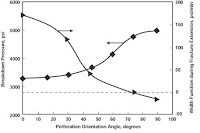
Figure 5-10 Fracture width performance and fracture initiation pressure as a function of perforation orientation relative to direction of in-situ stresses
Additionally, this experiment showed that fracture width is a function of perforation orientation. Figure 5-10 suggests that the optimal perforation phasing is 60° (equivalent to at most 30° deviation from the fracture direction) or less, at which the breakdown pressure is minimal. For an explanation of the negative widths in Figure 5-10, the reader is referred to Abass et al. (1994).
Clustered Perforations for Fracturing Deviated Wells
Clustered perforations can produce a transverse fracture perpendicular to the wellbore. A short perforated interval of 1 to 2 ft with 24 shots/ft can help reduce the occurrence of multiple fractures. A prefracturing stage of hydrochloric acid (HCl) in the treatment program can help establish a better communication channel between the wellbore and the main fracture.
Hydrojetting with HCl for Fracturing Horizontal Wells
Hydrojetting can ease the near-wellbore stress concentration, resulting in a successful fracturing treatment (Haigist et al., 1995). Figure 5-11 presents the sequence of operations for creating a single fracture from a horizontal well.
Figure

Figure 5-11 Hydrojetting and acid
Oriented Perforations for Sand Control
As previously explained, a circular wellbore in a rock formation creates a new stress field around the wellbore, which causes oriented failure (breakout) or total collapse (washout). Oriented perforations can be used for breakouts or unconsolidated formations.
Consolidated Formations
If breakout exists in a consolidated formation, the following steps are recommended (Figure 5-12):
• The near-wellbore area should be consolidated with a liquid resin material that is injected into the payzone.
• Because the breakout is oriented in the direction of minimum horizontal stress, a 180° phasing should be performed in the direction of maximum horizontal stress.
• A hydraulic fracture using a fracpack design should be performed.

Figure 5-12 Oriented perforation for sand control, where the
breakout region is left undisturbed
Unconsolidated Formations
Experiments showed that a wellbore should not be drilled through an unconsolidated formation because it would create a concentrated stress field around the wellbore. The hydrocarbon can be produced through hydraulic fracturing, whether in a vertical or a horizontal well. In a horizontal well, the perforation can be oriented in the lower side (Figure 5-13).

Figure 5-13 Experimental demonstration of drilling in the boundary layer and the use of oriented perforation and fracture to communicate with the poorly consolidated sandstones (sand production exclusion)
Based on fracture propagation mechanics, the fracture will have two wings in homogeneous formation even if it is forced to propagate in one direction (Figure 5-14).

Figure 5-14 Two-wing fracture propagating from one perforation
tunnel
Figure 5-13 demonstrates this concept, where a horizontal well was drilled in a homogeneous formation (hydrostone) with zero-phasing perforations in the lower side of the wellbore. A fracture was then initiated, and two fracture wings were created. However, when one wing of the fracture encountered a medium with less resistance to fracture propagation (lower fracture toughness), the upward fracture wing stopped and the lower one continued to propagate. The disturbance of energy required for fracture propagation works favorably in the technique above.
Fracpacks
From a rock mechanics perspective, the fracpack helps reduce near-wellbore pressure drawdown, which in turn reduces or prevents cohesive failure (erosion) and tensile failure. A combination fracpack/gravel pack can often effectively control sand production in many areas.
Figure 5-22 shows a hydraulic fracturing experiment in a poorly consolidated outcropping sample that has a Young's modulus of 377,000 psi and a compressive strength of 1037 psi.

Figure 5-22 Laboratory demonstration of fracturing poorly consolidated sandstone formations
This figure shows that a poorly consolidated formation can be fractured just like any conventional formation. The fracture length should be optimized to reduce the severe near-wellbore pressure drawdown (Abass et al.,1994; Fletcher et al.,1995).
Chemical Effects
A sandstone material's granular framework and type of natural cementation are inherent characteristics that help maintain stability; drilling a wellbore in the formation and introducing foreign fluids disturbs this natural stability. This section discusses the effect of drilling and completion fluids on the natural cementation material and describes a new means of restoring cementation during drilling.
Mineralogical analyses of most sand formations will reveal quartz, feldspar, carbonate (such as dolomite), and clay (such as chlorite, smectite). Cementation materials, such as quartz, dolomite, and chlorite, provide stability to a given formation and therefore should be maintained during drilling, completion, and stimulation phases.
Yale et al. (1995) studied the effects of cementation on the difference between the static and dynamic mechanical properties. The most interesting finding is the relation between the degree of nonlinearity and the static/dynamic ratio of mechanical properties. In other words, the type of cementation controls whether the material exhibits linear elastic, nonlinear elastic, or elastoplastic behavior during loading and unloading. Since a formation is exposed to many loading and unloading cycles during wellbore construction phases, studying a formation's loading and unloading characteristics is important. For exclusive sand control, the following techniques can be used individually or in combination depending on the failure mechanism:
• A horizontal wellbore in the boundary layer and a fracture to the formation
• Oriented perforations in the direction of maximum horizontal stress
• Fracpack and/or gravel pack
• Fracpack with resin-coated sand
• Consolidation during drilling
• Consolidation and fracpack
source: Petroleum well construction
• The use of clean, low-solids-content, compatible completion fluids
• The use of underbalanced perforations, such as 500 psi in oil wells and
1500 psi in gas wells
• The use of small charges, minimizing the effect of the compacted area (stress cage) around a perforation tunnel, which can reduce the original permeability as much as a factor of 10 or more
McLeod (1982) showed that the skin caused by the compacted zone could be very large.
The purpose of perforating should be defined clearly and designed appropriately. The perforation design should be evaluated based on the expected well completion and stimulation activity (Morita and McLeod, 1994). The purposes of perforating are listed below:
• Perforation as a completion method only or with the intention of matrixStimulation
• Perforation with the intention to gravel-pack
• Perforation for hydraulic fracturing (proppant or acid fracturing)
The perforation process will be discussed thoroughly in Perforating. This chapter will only discuss oriented perforations relative to the in-situ stresses.
This concept has been introduced to solve critical problems encountered during wellbore construction.
Oriented Perforations for Hydraulic Fracturing
Experimental and theoretical work indicates that perforation orientations should be designed to eliminate problems in fracturing vertical and deviated wells (Morita and McLeod, 1994; Behrmann and Elbel, 1991; Abass et al., 1994; Venditto et al., 1993). For a successful hydraulic fracturing treatment, perforation should be in phase with the anticipated fracture direction (the direction of maximum horizontal stress). This condition will
• Obtain maximum fracture width near the wellbore
• Create a single fracture
• Reduce the breakdown and propagation pressures
Figure 5-9 presents experimental results that show a complex fracture system in which the perforations are oriented within certain angles from the fracture direction (Abass et al., 1994).

Figure 5-9 Near wellbore fracture geometry as a function of perforation orientation relative to direction of in-situ stresses
The experimental study was conducted with hydrostone samples to study the effects of oriented perforations in the high and low sides of the horizontal well in the direction of the anticipated fracture. Figure 5-10 shows that for perforation angles of 0, 15, and 30°, the average breakdown pressure was 3200 psi; this pressure steadily increased for angles higher than 30°.

Figure 5-10 Fracture width performance and fracture initiation pressure as a function of perforation orientation relative to direction of in-situ stresses
Additionally, this experiment showed that fracture width is a function of perforation orientation. Figure 5-10 suggests that the optimal perforation phasing is 60° (equivalent to at most 30° deviation from the fracture direction) or less, at which the breakdown pressure is minimal. For an explanation of the negative widths in Figure 5-10, the reader is referred to Abass et al. (1994).
Clustered Perforations for Fracturing Deviated Wells
Clustered perforations can produce a transverse fracture perpendicular to the wellbore. A short perforated interval of 1 to 2 ft with 24 shots/ft can help reduce the occurrence of multiple fractures. A prefracturing stage of hydrochloric acid (HCl) in the treatment program can help establish a better communication channel between the wellbore and the main fracture.
Hydrojetting with HCl for Fracturing Horizontal Wells
Hydrojetting can ease the near-wellbore stress concentration, resulting in a successful fracturing treatment (Haigist et al., 1995). Figure 5-11 presents the sequence of operations for creating a single fracture from a horizontal well.
Figure

Figure 5-11 Hydrojetting and acid
Oriented Perforations for Sand Control
As previously explained, a circular wellbore in a rock formation creates a new stress field around the wellbore, which causes oriented failure (breakout) or total collapse (washout). Oriented perforations can be used for breakouts or unconsolidated formations.
Consolidated Formations
If breakout exists in a consolidated formation, the following steps are recommended (Figure 5-12):
• The near-wellbore area should be consolidated with a liquid resin material that is injected into the payzone.
• Because the breakout is oriented in the direction of minimum horizontal stress, a 180° phasing should be performed in the direction of maximum horizontal stress.
• A hydraulic fracture using a fracpack design should be performed.

Figure 5-12 Oriented perforation for sand control, where the
breakout region is left undisturbed
Unconsolidated Formations
Experiments showed that a wellbore should not be drilled through an unconsolidated formation because it would create a concentrated stress field around the wellbore. The hydrocarbon can be produced through hydraulic fracturing, whether in a vertical or a horizontal well. In a horizontal well, the perforation can be oriented in the lower side (Figure 5-13).

Figure 5-13 Experimental demonstration of drilling in the boundary layer and the use of oriented perforation and fracture to communicate with the poorly consolidated sandstones (sand production exclusion)
Based on fracture propagation mechanics, the fracture will have two wings in homogeneous formation even if it is forced to propagate in one direction (Figure 5-14).

Figure 5-14 Two-wing fracture propagating from one perforation
tunnel
Figure 5-13 demonstrates this concept, where a horizontal well was drilled in a homogeneous formation (hydrostone) with zero-phasing perforations in the lower side of the wellbore. A fracture was then initiated, and two fracture wings were created. However, when one wing of the fracture encountered a medium with less resistance to fracture propagation (lower fracture toughness), the upward fracture wing stopped and the lower one continued to propagate. The disturbance of energy required for fracture propagation works favorably in the technique above.
Fracpacks
From a rock mechanics perspective, the fracpack helps reduce near-wellbore pressure drawdown, which in turn reduces or prevents cohesive failure (erosion) and tensile failure. A combination fracpack/gravel pack can often effectively control sand production in many areas.
Figure 5-22 shows a hydraulic fracturing experiment in a poorly consolidated outcropping sample that has a Young's modulus of 377,000 psi and a compressive strength of 1037 psi.

Figure 5-22 Laboratory demonstration of fracturing poorly consolidated sandstone formations
This figure shows that a poorly consolidated formation can be fractured just like any conventional formation. The fracture length should be optimized to reduce the severe near-wellbore pressure drawdown (Abass et al.,1994; Fletcher et al.,1995).
Chemical Effects
A sandstone material's granular framework and type of natural cementation are inherent characteristics that help maintain stability; drilling a wellbore in the formation and introducing foreign fluids disturbs this natural stability. This section discusses the effect of drilling and completion fluids on the natural cementation material and describes a new means of restoring cementation during drilling.
Mineralogical analyses of most sand formations will reveal quartz, feldspar, carbonate (such as dolomite), and clay (such as chlorite, smectite). Cementation materials, such as quartz, dolomite, and chlorite, provide stability to a given formation and therefore should be maintained during drilling, completion, and stimulation phases.
Yale et al. (1995) studied the effects of cementation on the difference between the static and dynamic mechanical properties. The most interesting finding is the relation between the degree of nonlinearity and the static/dynamic ratio of mechanical properties. In other words, the type of cementation controls whether the material exhibits linear elastic, nonlinear elastic, or elastoplastic behavior during loading and unloading. Since a formation is exposed to many loading and unloading cycles during wellbore construction phases, studying a formation's loading and unloading characteristics is important. For exclusive sand control, the following techniques can be used individually or in combination depending on the failure mechanism:
• A horizontal wellbore in the boundary layer and a fracture to the formation
• Oriented perforations in the direction of maximum horizontal stress
• Fracpack and/or gravel pack
• Fracpack with resin-coated sand
• Consolidation during drilling
• Consolidation and fracpack
source: Petroleum well construction
Fracing improve opportunity in oil and gas
One of the two most important technologies in the development of the natural gas market in the last few years is “multi-stage fracing” (pronounced “fracking”), which is short for fracturing, as in fracturing the rock in which the oil and gas is held. (The other technology is Liquid Natural Gas, or LNG).
Fracing is sending a specially designed fluid down the oil or gas well
at high pressure and blowing it out into the reservoir rock to create cracks and channels through which the hydrocarbons can get to the well. How big an impact has multi-stage fracing [MSF] had? Once the industry figured out how to frac the shale rock formations to get at all the natural gas they hold, it opened up huge new reservoirs across North America, and is the leading reason on the supply side as to why the price of natural gas has plummeted.
It’s exciting for the industry and investors because improvements to MSF are still being made - the industry is continually getting more production, more fracs, or stages, per well. Initial fracing was done in 4 stages over 500 meters. Now you can see 16 stages over a 1600 metre horizontal length. (One active fracing company said this week that the average Montney well has 7-12 fracs).
The industry hasn’t hit the end of what MSF can do; innovation is still happening. And they’re fracing tighter and narrower reservoirs or payzones. One of the largest oil discoveries in North America is the Bakken play, which straddles the Dakotas and Saskatchewan (the U.S. Geological Society estimates over billion barrels are there) - but the zone can often be as narrow as 3 metres, or 9.5 feet. And a properly fraced horizontal well greatly improves economics. A frac can create kilometers of contact area for the oil or gas to flow into the well. Even though it costs twice as much as a vertical well, production can increase 400-700% and give payback to the operator in only a few months.
But a picture says 1000 words. To really understand visually what multi stage fracing is, see this video.
When I’m doing my research for the stocks in my portfolio, one of my key questions for any management team is - how large an undeveloped land package do you have in oil or gas formations that would use MSF? It’s also why, at any given time, the many oil and gas analysts and fund managers across North America, are studying how successfully energy producers are using MSF. Most analysts rate companies that use MSF as their top stock picks.They are writing entire research reports on the topic. Whenever an oil/gas producer reports their quarterlies, analysts ask how many horizontal wells, how many fracs, or stages, per well.
Fracing is so specialized that there are entire public companies dedicated to just that, such as Calfrac Well Services (CFWFF.PK), Canyon Services Group (FRC-TSX; $2.30) and Trican Well Services (TOLWF.PK). This brief article is meant to give retail investors just a quick look into a technology that is changing the industry and stock valuations.
“The changes in fracing in the last four years is mind boggling,” one industry executive told me. It used to be two to four trucks and a water tank, on one acre. Now it’s at least 10 trucks, multiple tanks holding various fluids, all on about eight acres.
While completing the frac itself is now done in a single day, he says… “The logistics and planning a frac job are now unbelievable. It’s now a two month job, getting the water setup, sand and equipment into location and recycling all the water.”
“And the geology of the rock now being drilled has changed. It used to be high porosity and permeability. Not anymore.”
Porosity is the volume of spaces within rock that might contain oil and gas. Permeability is how easily the oil or gas can flow through the rock.
For permeability, think of it this way - when a wave washes over beach sand the water flows through the sand this is - highly permeable. Most of the “easy” oil and gas has come from rocks like that; it’s the low hanging fruit. And in North America anyway, almost all of that is gone.
Now think of a solid granite countertop. That is not so permeable. That rock is “tight”, hence the name “tight gas”. The big exciting shale gas plays that have huge reserves and produce big boomer wells come from this type of tight rock.
The permeability of the shale gas host rock is 1/1000ths or less of what the type of reservoirs that were drilled only a decade ago. There are a few new reservoirs being found in the world with porosities of 30%. But all the new shale gas is in the order of 1%.
The key to getting that oil and gas out is knowing how to frac it. Fracing is an art as much as a science. Now if you if you drop a granite countertop, it shatters into 1000 pieces. If you could put every piece back together, you could still see the cracks around each piece. Those cracks are where the oil & gas would flow.
This is what fracing is doing the shale. It is exploiting natural cracks that exist in the rocks by reopening them and allowing flow.
One of the big differences in fracing from years ago is the fluids. A “cube” is 1000 litres of fluid which is pumped over time, and fracing companies used to send 2.5 cubes per minute of highly viscous (gooey, Jello like) fluid down a normal vertical well bore.
Now the rate they send fluid down a hole is more than 5x that, at 16 cubes. Companies have to be careful not to interfere the surrounding layers of rock (formations), which may have different characteristics than the reservoir they were drilling for. Say, for example, the neighboring formation had a lot of water in it. If the frac is not controlled (too strong) it can break into the adjacent zone and all that formation water could flow into the well and ruin it.
The water used for the new tight gas is not viscous - it is treated to be slippery-slick so it can be pumped so quickly. The slick water is brought back up to surface after the frac and recycled.
The geology or size and type of the formation are key in determining how long a horizontal well will get and how many fracs, or stages, along the length of the horizontal well. The initial wells into a new formation, such as the ones that were drilled into the Haynesville Shale in Louisiana or the Horn River shale in Canada - can be expensive; over $10 million each.
The design is tweaked and the treatments altered to get the maximum amount of contact area in the rock for the oil and gas to flow out. As companies gain experience and build a database of knowledge, costs come down quickly.
Different fracing techniques do come out into the public domain, but slowly. If a company can figure out how to correctly frac a big play, it has a huge competitive advantage.
So what can investors take away from all this detail?
MSF has opened up huge new reservoirs of gas in North America. And it really hasn’t even been used that much outside of North America - so it has potential to create many trillion cubic feet of more economic gas around the globe.
The much larger wells that MSF creates is lowering the cost of production. And MSF is still improving - management teams are still getting more and more production out of tighter and narrower formations.
When investing in an oil and gas producer, ask them how much they use MSF, because the economics of these wells, when they hit, are much better than conventional vertical wells. Producers who are drilling formations that can’t use MSF will most likely be high cost producers in the future
Fracing is sending a specially designed fluid down the oil or gas well
at high pressure and blowing it out into the reservoir rock to create cracks and channels through which the hydrocarbons can get to the well. How big an impact has multi-stage fracing [MSF] had? Once the industry figured out how to frac the shale rock formations to get at all the natural gas they hold, it opened up huge new reservoirs across North America, and is the leading reason on the supply side as to why the price of natural gas has plummeted.
It’s exciting for the industry and investors because improvements to MSF are still being made - the industry is continually getting more production, more fracs, or stages, per well. Initial fracing was done in 4 stages over 500 meters. Now you can see 16 stages over a 1600 metre horizontal length. (One active fracing company said this week that the average Montney well has 7-12 fracs).
The industry hasn’t hit the end of what MSF can do; innovation is still happening. And they’re fracing tighter and narrower reservoirs or payzones. One of the largest oil discoveries in North America is the Bakken play, which straddles the Dakotas and Saskatchewan (the U.S. Geological Society estimates over billion barrels are there) - but the zone can often be as narrow as 3 metres, or 9.5 feet. And a properly fraced horizontal well greatly improves economics. A frac can create kilometers of contact area for the oil or gas to flow into the well. Even though it costs twice as much as a vertical well, production can increase 400-700% and give payback to the operator in only a few months.
But a picture says 1000 words. To really understand visually what multi stage fracing is, see this video.
When I’m doing my research for the stocks in my portfolio, one of my key questions for any management team is - how large an undeveloped land package do you have in oil or gas formations that would use MSF? It’s also why, at any given time, the many oil and gas analysts and fund managers across North America, are studying how successfully energy producers are using MSF. Most analysts rate companies that use MSF as their top stock picks.They are writing entire research reports on the topic. Whenever an oil/gas producer reports their quarterlies, analysts ask how many horizontal wells, how many fracs, or stages, per well.
Fracing is so specialized that there are entire public companies dedicated to just that, such as Calfrac Well Services (CFWFF.PK), Canyon Services Group (FRC-TSX; $2.30) and Trican Well Services (TOLWF.PK). This brief article is meant to give retail investors just a quick look into a technology that is changing the industry and stock valuations.
“The changes in fracing in the last four years is mind boggling,” one industry executive told me. It used to be two to four trucks and a water tank, on one acre. Now it’s at least 10 trucks, multiple tanks holding various fluids, all on about eight acres.
While completing the frac itself is now done in a single day, he says… “The logistics and planning a frac job are now unbelievable. It’s now a two month job, getting the water setup, sand and equipment into location and recycling all the water.”
“And the geology of the rock now being drilled has changed. It used to be high porosity and permeability. Not anymore.”
Porosity is the volume of spaces within rock that might contain oil and gas. Permeability is how easily the oil or gas can flow through the rock.
For permeability, think of it this way - when a wave washes over beach sand the water flows through the sand this is - highly permeable. Most of the “easy” oil and gas has come from rocks like that; it’s the low hanging fruit. And in North America anyway, almost all of that is gone.
Now think of a solid granite countertop. That is not so permeable. That rock is “tight”, hence the name “tight gas”. The big exciting shale gas plays that have huge reserves and produce big boomer wells come from this type of tight rock.
The permeability of the shale gas host rock is 1/1000ths or less of what the type of reservoirs that were drilled only a decade ago. There are a few new reservoirs being found in the world with porosities of 30%. But all the new shale gas is in the order of 1%.
The key to getting that oil and gas out is knowing how to frac it. Fracing is an art as much as a science. Now if you if you drop a granite countertop, it shatters into 1000 pieces. If you could put every piece back together, you could still see the cracks around each piece. Those cracks are where the oil & gas would flow.
This is what fracing is doing the shale. It is exploiting natural cracks that exist in the rocks by reopening them and allowing flow.
One of the big differences in fracing from years ago is the fluids. A “cube” is 1000 litres of fluid which is pumped over time, and fracing companies used to send 2.5 cubes per minute of highly viscous (gooey, Jello like) fluid down a normal vertical well bore.
Now the rate they send fluid down a hole is more than 5x that, at 16 cubes. Companies have to be careful not to interfere the surrounding layers of rock (formations), which may have different characteristics than the reservoir they were drilling for. Say, for example, the neighboring formation had a lot of water in it. If the frac is not controlled (too strong) it can break into the adjacent zone and all that formation water could flow into the well and ruin it.
The water used for the new tight gas is not viscous - it is treated to be slippery-slick so it can be pumped so quickly. The slick water is brought back up to surface after the frac and recycled.
The geology or size and type of the formation are key in determining how long a horizontal well will get and how many fracs, or stages, along the length of the horizontal well. The initial wells into a new formation, such as the ones that were drilled into the Haynesville Shale in Louisiana or the Horn River shale in Canada - can be expensive; over $10 million each.
The design is tweaked and the treatments altered to get the maximum amount of contact area in the rock for the oil and gas to flow out. As companies gain experience and build a database of knowledge, costs come down quickly.
Different fracing techniques do come out into the public domain, but slowly. If a company can figure out how to correctly frac a big play, it has a huge competitive advantage.
So what can investors take away from all this detail?
MSF has opened up huge new reservoirs of gas in North America. And it really hasn’t even been used that much outside of North America - so it has potential to create many trillion cubic feet of more economic gas around the globe.
The much larger wells that MSF creates is lowering the cost of production. And MSF is still improving - management teams are still getting more and more production out of tighter and narrower formations.
When investing in an oil and gas producer, ask them how much they use MSF, because the economics of these wells, when they hit, are much better than conventional vertical wells. Producers who are drilling formations that can’t use MSF will most likely be high cost producers in the future
Differential Pressure Sticking pada Drill Pipe Dan Drill Collars
Differential wall sticking dikarenakan oleh drill pipe atau drill collar menghalangi aliran dari fluida dari dasar lubang menuju ke formasi
Pada formasi yang permeable, dimana kolom hidrostatik lumpur lebih tinggi dari tekanan formasi , kehilamgan tekanan dapat diperhitungkan karena aliran fluida kedalam formasi disaring oleh batuan pada dinding sumur dan mengakibatkan terbentuknya filter cake.
Bagian permukaan peralatan yang licin, membantu efek pelekatan dari filter cake, membentuk penghalang pada fluid loss ke dalam formasi, tergantung dari panjang dari wilayah yang terhalangi dan perbedaan dalam lubang bor serta tekanan formasi, halangan terhadap fluida ini yang mengakibatkan terjadinya tenaga yang sangat besar terhadap peralatan, dan kemudian mengakibatkan differensial wall sticking pada drill string
Penggunaan dari packed hole assembly akan menghilangkan banyak kondisi yang berakibat pada pipe sticking dari drill stem dengan mencegah menyentuh dasar sumur, seperti bit stabilizing assemblies juga mencegah perubahan sudut lubang secara tiba-tiba, offset dan dogleg severity yang mengakibatkan sticking pada drill stem dalam key seat
Mengurangi Differential Pressure Sticking
Differential Pressure Sticking dapat dikurangi secara effektif dengan menggunakan peralatan berikut:
Hevi-WateT Drill Pipe (lihat gambar No. 01)
Alat ini digabungkan pada akhir untuk melengkapi upset ditengah tube dan bertindak sebagai centralizers untuk menyangga bagian heavy-wall dari dinding lubang.
Spiral or Grooved Drill Collars (lihat gambar No. 01)
Alat ini memberikan luas bidang sentuhan yang kecil pada dinding sumur. Juga membiarkan fkuida untuk melewati dan menyamakan tekanan lubang bor sepanjang collar. Seluruh box end pada semua ukuran dibiarkan tidak terpotong untuk jarak kurang dari 18 in. (457 mm) dan tidak lebih dari 24 in. (610 mm) dibawah pundak. Seluruh pin end pada semua ukuran dibiarkan tidak terpotong untuk jarak kurang dari 12 in. (305 mm) dan tidak lebih dari 22 in. (559 mm) dibawah pundak.
Stabilizers (lihat gambar No. 01)
Stabilizers diposisikan antara drill stem adalah cara positif lainnya untuk mencegah differential sticking. Rotating blade, welded blade dan nonrotating sleeve-type stabilizers digunakan untuk memastikan drill collar berada ditengah lubang. Pemilihan tipe dari stabilizer dan penempatannya pada drill stem dapat merubah kemampuan penembusan pada formation yang sedang dibor, serta ukuran lubang, etc.

Disadur dari: Drilling Assembly handbook 2001.pdf, www.smith.com

Free Signature Generator
Pada formasi yang permeable, dimana kolom hidrostatik lumpur lebih tinggi dari tekanan formasi , kehilamgan tekanan dapat diperhitungkan karena aliran fluida kedalam formasi disaring oleh batuan pada dinding sumur dan mengakibatkan terbentuknya filter cake.
Bagian permukaan peralatan yang licin, membantu efek pelekatan dari filter cake, membentuk penghalang pada fluid loss ke dalam formasi, tergantung dari panjang dari wilayah yang terhalangi dan perbedaan dalam lubang bor serta tekanan formasi, halangan terhadap fluida ini yang mengakibatkan terjadinya tenaga yang sangat besar terhadap peralatan, dan kemudian mengakibatkan differensial wall sticking pada drill string
Penggunaan dari packed hole assembly akan menghilangkan banyak kondisi yang berakibat pada pipe sticking dari drill stem dengan mencegah menyentuh dasar sumur, seperti bit stabilizing assemblies juga mencegah perubahan sudut lubang secara tiba-tiba, offset dan dogleg severity yang mengakibatkan sticking pada drill stem dalam key seat
Mengurangi Differential Pressure Sticking
Differential Pressure Sticking dapat dikurangi secara effektif dengan menggunakan peralatan berikut:
Hevi-WateT Drill Pipe (lihat gambar No. 01)
Alat ini digabungkan pada akhir untuk melengkapi upset ditengah tube dan bertindak sebagai centralizers untuk menyangga bagian heavy-wall dari dinding lubang.
Spiral or Grooved Drill Collars (lihat gambar No. 01)
Alat ini memberikan luas bidang sentuhan yang kecil pada dinding sumur. Juga membiarkan fkuida untuk melewati dan menyamakan tekanan lubang bor sepanjang collar. Seluruh box end pada semua ukuran dibiarkan tidak terpotong untuk jarak kurang dari 18 in. (457 mm) dan tidak lebih dari 24 in. (610 mm) dibawah pundak. Seluruh pin end pada semua ukuran dibiarkan tidak terpotong untuk jarak kurang dari 12 in. (305 mm) dan tidak lebih dari 22 in. (559 mm) dibawah pundak.
Stabilizers (lihat gambar No. 01)
Stabilizers diposisikan antara drill stem adalah cara positif lainnya untuk mencegah differential sticking. Rotating blade, welded blade dan nonrotating sleeve-type stabilizers digunakan untuk memastikan drill collar berada ditengah lubang. Pemilihan tipe dari stabilizer dan penempatannya pada drill stem dapat merubah kemampuan penembusan pada formation yang sedang dibor, serta ukuran lubang, etc.

Disadur dari: Drilling Assembly handbook 2001.pdf, www.smith.com
Free Signature Generator
Rock Bit Optimasi
Rock bits didesain untu berputar dalam sudut lubang bor. Umur dari bit tersebut berkurang apabila sudutnya salah. Kesalahan sudut ini bias dalam bentuk parallel atau angular. ketika sudut dari lubang berubah dalam keadaan pararel, bit akan keluar dari pusatnya (lihat Gambar No. 1). Hal ini mengakibatkan struktur cutting terlihat seperti pecahan. Lingkaran dari dasar yang tidak tergerus berkembang serta umur dari bit secara drastis berkurang jika drill collar berada tepat diatas bit dan menghantam dinding sumur, kesalahan angular terjadi. Performa bit bergantung pada derajat kesalahannya. Sebagai contoh dalam lubang 83/4 in. (222.3 mm) hole, collar 7 in. (177.8 mm) mengurangi efek dari sudut , akan tetapi kesalahan masih dapat terjadi. Kesalahan Angular memperbolehkan dua efek yang sangat berbahaya jika terjadi. Pertama, berat bit dipindahkan dari satu cone ke cone lainnya, yang mengakibatkan kecepatan kerusakan struktur gigi dan bearing. Berat seharusnya di distribusikan kepada tiga cone. Efek jelek yang kedua adalah kerusakan vital bentuk cutting yang berakibat pada bagian atas luar dari baris gigi. Cone “Apple-shape” terjadi dan berakibat menderitanya bit secara hebat lihat Gambar No.3). perbaikan dramastis pada umur bit telah diperiksa pada bagian bottom hole assembly yang tidak stabil sampai bagian bottom-hole assembly yang stabil, terutama ketika diamond bits, PDC bits, journal bearing atau sealed bearing bits sedang dijalankan.
Hindari kesalahan baik angular maupun and parallel dengan pemilihan assembly yang menghasilkan kestabilan tinggi. Semakin besar derajat kestabilan, semakin besar keuntungan.

Kesalahan parallel
dikarenakan oleh penggunaan dari drill collar yang terlalu kecil (tidak sebanding dengan ukuran lubang) dan tidak stabil. Bit dapat bergerak keluar dari titik pusat sampai OD drill collar bersentuhan dengan dinding lubang. Hal ini mengakibatkan kerugian karena pemboran menyimpang dari titik pusat.
Kesalahan angular
Dikarenakan oleh penggunaan drill collar (dalam hubungannya dengan ukuran lubang) dan tanpa kestabilan. Kebanyakan bit menekan pada satu cone setiap waktu, menyebabkan kecepatan kerusakan baik pada struktur cutting maupun struktur bearing serta struktur bit.

Gambar No. 3 menunjukan foto dari kerusakan medium, pada formasi ringan ke medium karena bit menyimpang dari titik pusat. Catatan cone shell, diantara baris dari struktur cutting, telah tergerus oleh lingkaran dari formasi yang tidak terpotong pada dasar sumur.

Gambar No. 4 menunjukan foto dari bit yang mengalami kerusakan pada formasi medium karena kesalahan angular.

Gambar No. 5 menunjukan foto dari bit yang mengalami kerusakan karena tekanan dan OD dari bit itu sendiri. Kerusakan sangat parah sampai bagian bawah telah hilang serta beberapa roller bearing hilang. Bit digunakan pada formasi yang abrasive terlalu lama. Ketika bit ditarik hasilnya adalah seperti ini, bagian terakhir lubang harus dibor dengan metode undergage. Keseluruhan bagian lubang yang meruncing harus di reamer untuk menjalankan bit baru.

Gambar No. 6 menunjukan foto kerusakan medium, bit lunak ke medium telah dijalankan tanpa dukungan alat vibration dampener. vibration dampener dijalankan dalam bottom-hole assembly akan membantu mendapatkan rate of penetration lebih cepat dan menambah umur bit. Ketika membor diformasi keras, getaran yang dihasilkan berlebihan, bit bergetar dan getaran tersebut dapat menyebabkan gigi dan tungsten carbide mengalami kerusakan pada bagian bearing secara cepat. Karena dijalankan terlalu kasar pada beberapa formasi, berat yang diharapkan dan kecepatan putaran tidak dapat dimanfaatkan. Penggunaan dari vibration dampener akan menghilangkan terjadinya goncangan dan menjaga rate of penetration yang tinggi serta menambah umur bit.
Hindari kesalahan baik angular maupun and parallel dengan pemilihan assembly yang menghasilkan kestabilan tinggi. Semakin besar derajat kestabilan, semakin besar keuntungan.

Kesalahan parallel
dikarenakan oleh penggunaan dari drill collar yang terlalu kecil (tidak sebanding dengan ukuran lubang) dan tidak stabil. Bit dapat bergerak keluar dari titik pusat sampai OD drill collar bersentuhan dengan dinding lubang. Hal ini mengakibatkan kerugian karena pemboran menyimpang dari titik pusat.
Kesalahan angular
Dikarenakan oleh penggunaan drill collar (dalam hubungannya dengan ukuran lubang) dan tanpa kestabilan. Kebanyakan bit menekan pada satu cone setiap waktu, menyebabkan kecepatan kerusakan baik pada struktur cutting maupun struktur bearing serta struktur bit.

Gambar No. 3 menunjukan foto dari kerusakan medium, pada formasi ringan ke medium karena bit menyimpang dari titik pusat. Catatan cone shell, diantara baris dari struktur cutting, telah tergerus oleh lingkaran dari formasi yang tidak terpotong pada dasar sumur.

Gambar No. 4 menunjukan foto dari bit yang mengalami kerusakan pada formasi medium karena kesalahan angular.

Gambar No. 5 menunjukan foto dari bit yang mengalami kerusakan karena tekanan dan OD dari bit itu sendiri. Kerusakan sangat parah sampai bagian bawah telah hilang serta beberapa roller bearing hilang. Bit digunakan pada formasi yang abrasive terlalu lama. Ketika bit ditarik hasilnya adalah seperti ini, bagian terakhir lubang harus dibor dengan metode undergage. Keseluruhan bagian lubang yang meruncing harus di reamer untuk menjalankan bit baru.

Gambar No. 6 menunjukan foto kerusakan medium, bit lunak ke medium telah dijalankan tanpa dukungan alat vibration dampener. vibration dampener dijalankan dalam bottom-hole assembly akan membantu mendapatkan rate of penetration lebih cepat dan menambah umur bit. Ketika membor diformasi keras, getaran yang dihasilkan berlebihan, bit bergetar dan getaran tersebut dapat menyebabkan gigi dan tungsten carbide mengalami kerusakan pada bagian bearing secara cepat. Karena dijalankan terlalu kasar pada beberapa formasi, berat yang diharapkan dan kecepatan putaran tidak dapat dimanfaatkan. Penggunaan dari vibration dampener akan menghilangkan terjadinya goncangan dan menjaga rate of penetration yang tinggi serta menambah umur bit.
Logging while Drilling (LWD

Logging while drilling (LWD) adalah teknik untuk menyampaikan alat logging suur kedlam daras lubang sebagai bagian dari bottom hole assembly (BHA).
alat LWD bekerja dengan MWD system untuk mengirimkan sebagian atau keseluruhan hasil perhitungan ke lokasi permukaan melalui drilling mud pulser atau teknik yang lebih berkembang, sementara alat LWD tools masih ada didalam sumur yang biasa disebut "Real Time Data". perhitungan menyeluruh dapat ditemukan dari alat LWD setelah alat tersebut ditarik kepermukaan, yang disebut "Memory Data".
teknologi LWD dikembangkan dari teknologi logging sebelumnya sebagai was developed originally as an perangkat tambahan dari teknologi MWD sebelumnya untuk memenuhi atau mengganti sebagian operasi wireline logging operation. dengan pengembangan dari teknologi dekade sebelumnya, LWD sekarang digunakan secara meluas (termasuk geosteering), formation evaluasi (biasanya untuk real time dan sumur dengan sudut kemiringan tinggi diatas 45).
Perhitungan yang disediakan LWD
teknologi LWD sebenarnya dikembangkan secara sebagian atau keseluruhan untuk menggantikan wireline logging sehingga umumnya perhitungan yang tersedia pada LWD sama dengan wireline logging, beberapa perhitungan hanya didapatkan pada LWD, berikut adalah daftar dari perhitungan yang tersedia pada teknologi LWD
* Natural Gamma Ray (GR)
o Total Gamma Ray
o Spectral Gamma Ray
o Azimuthal Gamma Ray
o Gamma ray close to drill bit.
* Density and Photoelectric Index
* Neutron Porosity
* Borehole Caliper
o Ultra sonic azimuthal caliper.
o Density Caliper
* Resistivity (ohm-m)
o Attenuation and phase shift resistivities at different transmitter spacings and frequencies.
o Resistivity at the drill bit.
o Deep directional resistivities
* Sonic
o Compressional Slowness(Δtc)
o Shear Slowness (Δts)
* Borehole Images
o Density Borehole Image
o Resistivity Borehole Image
* Formation Tester and Sampler
o Formation Pressure
o Formation Fluid Sample
* Nuclear Magnetic Resonance (NMR)
* Seismic While Drilling (SWD)
o Drillbit-SWD
o VSP-WD (Vertical Seismic Profile While Drilling)
Free Signature Generator
How hydrocarbons were formed
Oil and gas are derived from organic materials that were deposited millions of years ago. Over time, these materials were buried and the soft sediments around them became rock layers. Under the right conditions of heat and pressure, those organic materials can be transformed to oil and gas in what are known as source rocks. Some of the oil and gas generated in the source rock escaped and flowed through layers of porous rock, such as limestones and sandstones. Individual pockets of hydrocarbons accumulated in porous reservoirs developed when the hydrocarbons were trapped under impermeable rock layers.
Understanding subsurface structures
During the early stages of searching for new fields, Shell explorationists must build up a thorough understanding of the overall basin to evaluate and grade the potential of the petroleum systems. Across the globe, we use consistent and highly effective methods to analyse these systems in which each play is unique. A technique we use to develop this understanding is known as play-based exploration – a technique that has increased our ability to make timely and high quality decisions
 Some of the oil and gas generated in the source rock escaped and flowed through layers of porous rock, such as limestones and sandstones. Individual pockets of hydrocarbons accumulated in porous reservoirs developed when the hydrocarbons were trapped under impermeable rock layers.
Understanding subsurface structures
During the early stages of searching for new fields, Shell explorationists must build up a thorough understanding of the overall basin to evaluate and grade the potential of the petroleum systems. Across the globe, we use consistent and highly effective methods to analyse these systems in which each play is unique. A technique we use to develop this understanding is known as play-based exploration – a technique that has increased our ability to make timely and high quality decisions
Lumpur pemboran
Lumpur menurut defenisi API adalah fluida sirkulasi yang digunakan dalam pemboran dan memiliki peranan pentinga dalam keberhasilan suatu proses pemboran itu sendiri
dari jenis pelarutnya lumpur dapat digolongkan menjadi:
* Fresh water mud (lumpur air tawar) dengan kadar garam 10000 ppm
lumpur jenis ini dibedakan menjadi:
- Spud mud: merupakan lumpur pemboran awal yang berguna untuk mengangkat cutting pada pemboran di trayek conductur cassing
- Natural mud: lumpur yang terbentuk dari pecahan cutting, digunakan pada pemboran trayek surface casing
- Bentonite mud: lumpur koloidal inorganic yang digunakan untuk menaikan viscositas & mengurangi ketebalan mud cake
- Phospate mud: lumpur dengan polyphospateyang digunakan untuk mengontrol viscositas, gel strength, filtration loss da mud cake yang tipis
- Organic mud: lumpur dengan pregelatined starch atau carboxy methil cellulose (CMC) untuk mengurangi filtration loss
- Red Mud: lumpur dengan polypospate, ph dibawah 10 dibuat dengan treatment caustic soda & quebranco
- Calcium mud: lumpur yang dibuat dengan penambahan calcium dari slake lime, plaster paris, dan dessicant
* Salt water mud: lumpur yang digunakan dalam pemboran pada salt dome, shale formation, atau salt stinger, ph dibawah 8 didapatkan dengan mengganti bentonite dengan attapulgite, jenisnya:
- Unsaturated salt water mud
- Saturated salt water mud
- Sodium sillicate
* Oil in water emulsion mud: lumpur ini dibuat dengan minyak solar sebagai emulsi terhadap air, keuntungan lumpur jenis iiadalah mengurangi korosi pada drill string, memperbaiki sifat lumpur, mengurangi balling (melekatnya lumpur pada drill string), dibuat dengan menambahkan 5-25% volume minyak terhadap air
* Oil base mud; lumpur dengan bahan dasar minyak sebagai fase kontinyu dan air sebagai emulsier (5-15% volume) manfaatnya menghidratkan shale/clay yang sensitif terhadap air..... walaupun sekarang sudah mulai berkurang karena terganti oleh KCl polimer mud.
* Gaseous drilling fluid: lumpur yang dibuat dengan mencampurkan gas diatomik seperti N2, CO2, H2, untuk formasi yang keras dan keing kelebihan lumpur ini adalah dapat diproduksikannya gas liar (methane) pada formasi cavern yang tertembus lubang bor selama pemboran tanpa khawatir terjadi kick, digunakan luas pada daerah pemboran middle east
dari jenis pelarutnya lumpur dapat digolongkan menjadi:
* Fresh water mud (lumpur air tawar) dengan kadar garam 10000 ppm
lumpur jenis ini dibedakan menjadi:
- Spud mud: merupakan lumpur pemboran awal yang berguna untuk mengangkat cutting pada pemboran di trayek conductur cassing
- Natural mud: lumpur yang terbentuk dari pecahan cutting, digunakan pada pemboran trayek surface casing
- Bentonite mud: lumpur koloidal inorganic yang digunakan untuk menaikan viscositas & mengurangi ketebalan mud cake
- Phospate mud: lumpur dengan polyphospateyang digunakan untuk mengontrol viscositas, gel strength, filtration loss da mud cake yang tipis
- Organic mud: lumpur dengan pregelatined starch atau carboxy methil cellulose (CMC) untuk mengurangi filtration loss
- Red Mud: lumpur dengan polypospate, ph dibawah 10 dibuat dengan treatment caustic soda & quebranco
- Calcium mud: lumpur yang dibuat dengan penambahan calcium dari slake lime, plaster paris, dan dessicant
* Salt water mud: lumpur yang digunakan dalam pemboran pada salt dome, shale formation, atau salt stinger, ph dibawah 8 didapatkan dengan mengganti bentonite dengan attapulgite, jenisnya:
- Unsaturated salt water mud
- Saturated salt water mud
- Sodium sillicate
* Oil in water emulsion mud: lumpur ini dibuat dengan minyak solar sebagai emulsi terhadap air, keuntungan lumpur jenis iiadalah mengurangi korosi pada drill string, memperbaiki sifat lumpur, mengurangi balling (melekatnya lumpur pada drill string), dibuat dengan menambahkan 5-25% volume minyak terhadap air
* Oil base mud; lumpur dengan bahan dasar minyak sebagai fase kontinyu dan air sebagai emulsier (5-15% volume) manfaatnya menghidratkan shale/clay yang sensitif terhadap air..... walaupun sekarang sudah mulai berkurang karena terganti oleh KCl polimer mud.
* Gaseous drilling fluid: lumpur yang dibuat dengan mencampurkan gas diatomik seperti N2, CO2, H2, untuk formasi yang keras dan keing kelebihan lumpur ini adalah dapat diproduksikannya gas liar (methane) pada formasi cavern yang tertembus lubang bor selama pemboran tanpa khawatir terjadi kick, digunakan luas pada daerah pemboran middle east
BARIT SEBAGAI BAHAN ADITIF LUMPUR
Pemakaian lumpur pemboran pada proses pemboran minyak bumi merupakan suatu hal yang sangat penting untuk mempermudah penetrasi mata bor pada batuan, menahan tekanan formasi yang tidak normal, menjaga mata bor tetap dingin dan agar
bisa mengeluarkan serbuk pemboran (cutting). Pemakaian lumpur pemboran ini dikembangkan dari prinsip penggunaan sirkulasi air yang menerus melewati pipa bor
untuk memindahkan serbuk bor dari dasar lubang ke permukaan yang pertama kali
dilaporkan pertama kalinya pada tahun 1845 oleh insinyur berkebangsaan Perancis.
Penggunaan lumpur pemboran sendiri dikenal sejak dimulainya pemboran putar (rotary drilling) pada tahun 1887 dengan fungsi awalnya hanya untuk memindahkan cutting dari dasar lubang bor ke atas permukaan. Semakin berkembangnya metode pemboran memberi pengaruh terhadap perkembangan lumpur pemboran. Pada masa sekarang ini jenis-jenis lumpur bor yang umum digunakan, yaitu water base mud dan oil base mud, disamping itu dikenal juga gas base mud yang jarang digunakan. Lumpur bor yang pada awalnya hanya menggunakan bahan lempung sekarang ini telah menggunakan berbagai jenis aditif untuk meningkatkan kekentalan dan berat jenisnya.
Salah satu zat aditif yang digunakan adalah barit karena dapat menaikkan densitas lumpur bor baik oil base mud maupun water base mud, agar mampu mengimbangi/menahan tekanan pada formasi yang tinggi. Kemampuan barit untuk
menaikkan densitas lumpur bor ini karena didukung berat jenis barit yang tergolong besar, yaitu 4,2 – 4,6.
Description Alternative :
Pemakaian lumpur pemboran pada proses pemboran minyak bumi merupakan suatu hal yang sangat penting untuk mempermudah penetrasi mata bor pada batuan, menahan tekanan formasi yang tidak normal, menjaga mata bor tetap dingin dan agar
bisa mengeluarkan serbuk pemboran (cutting). Pemakaian lumpur pemboran ini dikembangkan dari prinsip penggunaan sirkulasi air yang menerus melewati pipa bor
untuk memindahkan serbuk bor dari dasar lubang ke permukaan yang pertama kali
dilaporkan pertama kalinya pada tahun 1845 oleh insinyur berkebangsaan Perancis.
Penggunaan lumpur pemboran sendiri dikenal sejak dimulainya pemboran putar (rotary drilling) pada tahun 1887 dengan fungsi awalnya hanya untuk memindahkan cutting dari dasar lubang bor ke atas permukaan. Semakin berkembangnya metode pemboran memberi pengaruh terhadap perkembangan lumpur pemboran. Pada masa sekarang ini jenis-jenis lumpur bor yang umum digunakan, yaitu water base mud dan oil base mud, disamping itu dikenal juga gas base mud yang jarang digunakan. Lumpur bor yang pada awalnya hanya menggunakan bahan lempung sekarang ini telah menggunakan berbagai jenis aditif untuk meningkatkan kekentalan dan berat jenisnya.
Salah satu zat aditif yang digunakan adalah barit karena dapat menaikkan densitas lumpur bor baik oil base mud maupun water base mud, agar mampu mengimbangi/menahan tekanan pada formasi yang tinggi. Kemampuan barit untuk
menaikkan densitas lumpur bor ini karena didukung berat jenis barit yang tergolong besar, yaitu 4,2 – 4,6.
bisa mengeluarkan serbuk pemboran (cutting). Pemakaian lumpur pemboran ini dikembangkan dari prinsip penggunaan sirkulasi air yang menerus melewati pipa bor
untuk memindahkan serbuk bor dari dasar lubang ke permukaan yang pertama kali
dilaporkan pertama kalinya pada tahun 1845 oleh insinyur berkebangsaan Perancis.
Penggunaan lumpur pemboran sendiri dikenal sejak dimulainya pemboran putar (rotary drilling) pada tahun 1887 dengan fungsi awalnya hanya untuk memindahkan cutting dari dasar lubang bor ke atas permukaan. Semakin berkembangnya metode pemboran memberi pengaruh terhadap perkembangan lumpur pemboran. Pada masa sekarang ini jenis-jenis lumpur bor yang umum digunakan, yaitu water base mud dan oil base mud, disamping itu dikenal juga gas base mud yang jarang digunakan. Lumpur bor yang pada awalnya hanya menggunakan bahan lempung sekarang ini telah menggunakan berbagai jenis aditif untuk meningkatkan kekentalan dan berat jenisnya.
Salah satu zat aditif yang digunakan adalah barit karena dapat menaikkan densitas lumpur bor baik oil base mud maupun water base mud, agar mampu mengimbangi/menahan tekanan pada formasi yang tinggi. Kemampuan barit untuk
menaikkan densitas lumpur bor ini karena didukung berat jenis barit yang tergolong besar, yaitu 4,2 – 4,6.
Description Alternative :
Pemakaian lumpur pemboran pada proses pemboran minyak bumi merupakan suatu hal yang sangat penting untuk mempermudah penetrasi mata bor pada batuan, menahan tekanan formasi yang tidak normal, menjaga mata bor tetap dingin dan agar
bisa mengeluarkan serbuk pemboran (cutting). Pemakaian lumpur pemboran ini dikembangkan dari prinsip penggunaan sirkulasi air yang menerus melewati pipa bor
untuk memindahkan serbuk bor dari dasar lubang ke permukaan yang pertama kali
dilaporkan pertama kalinya pada tahun 1845 oleh insinyur berkebangsaan Perancis.
Penggunaan lumpur pemboran sendiri dikenal sejak dimulainya pemboran putar (rotary drilling) pada tahun 1887 dengan fungsi awalnya hanya untuk memindahkan cutting dari dasar lubang bor ke atas permukaan. Semakin berkembangnya metode pemboran memberi pengaruh terhadap perkembangan lumpur pemboran. Pada masa sekarang ini jenis-jenis lumpur bor yang umum digunakan, yaitu water base mud dan oil base mud, disamping itu dikenal juga gas base mud yang jarang digunakan. Lumpur bor yang pada awalnya hanya menggunakan bahan lempung sekarang ini telah menggunakan berbagai jenis aditif untuk meningkatkan kekentalan dan berat jenisnya.
Salah satu zat aditif yang digunakan adalah barit karena dapat menaikkan densitas lumpur bor baik oil base mud maupun water base mud, agar mampu mengimbangi/menahan tekanan pada formasi yang tinggi. Kemampuan barit untuk
menaikkan densitas lumpur bor ini karena didukung berat jenis barit yang tergolong besar, yaitu 4,2 – 4,6.


Langganan:
Postingan (Atom)


